Synchronous counter in digital electronics with circuit diagram Circuit diagram 4 bit binary counter Mod counters are truncated modulus counters
Using the following circuit, design a mod-10 up and | Chegg.com
Electronic – problem with the 74160 decade counter – valuable tech notes
State diagram for 4 bit counter
Solved draw the circuit for a mod-10 counter (also known asDesign a synchronous bcd counter Mod 10 synchronous counter updatedAsynchronous up down counter circuit diagram.
Solved problem 4 (10 pts) • complete the timing diagram of10+ program counter diagram Asynchronous counter2: implement and simulate a mod-10 (decade) counter,.

Solved instruction : design a mod 10 counter using jk
Mod counters are truncated modulus countersMod 5 asynchronous counter circuit diagram Counters modulo modulus tutorials truncatedDesign a mod-5 synchronous counter using d flip flop.
Electronic – how to i make the mod 10 up/down counter wrap from 0 to 9Bcd ripple counter (with simulation) Solved a. explain the operation of the circuit using aCounter ripple multisim.
Solved complete the circuit diagram for a mod-8 synchronous
Design mod 5 asynchronous counter using jk flip flopModulo 6 counter jk flip flops Mod 10 counter circuit diagramMod 10 ripple counter.
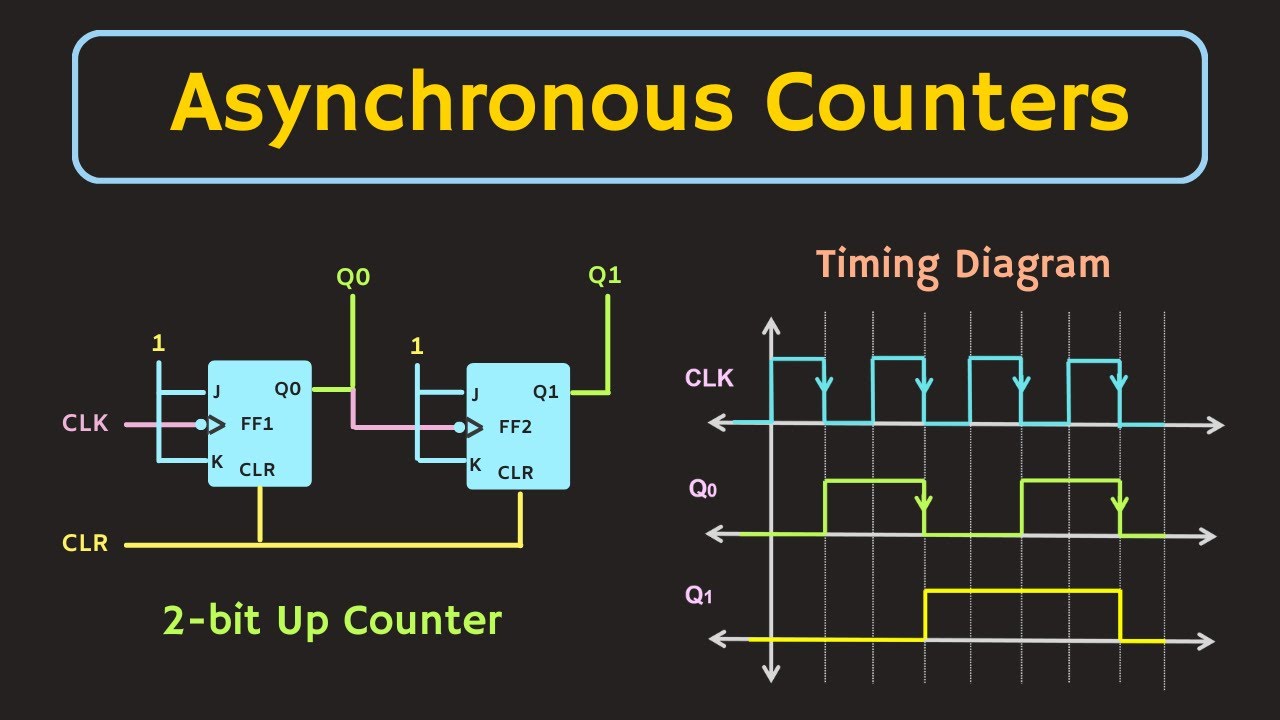
Asynchronous up down counter circuit diagramF-alpha.net: experiment 5 3 bit up down counter state diagramCounter mod modulus counters truncated electronics decade.

Solved: question 1: draw the circuit and timing diagram for a mod 7
Logic diagram of 4 bit asynchronous counter7490 decade counter circuit (mod-10) designing » counter circuits Using the following circuit, design a mod-10 up andCounter circuit mod load decade enable parallel known draw also dn qo diagram transcribed text show solved block clock.
4 bit counter schematicWhy are mod-10 & mod-5 decade counters while mod-6 & mod-8 not? Counter 7490 decade circuits.